

The instrumentation amplifier (IA) is an integrated combination of op amps and feedback resistors used to accurately acquire and amplify signals.
Don’t know about instrumentation amps? Get a very quick start here.
A common mistake in using these versatile amplifiers is to fail to provide a path for input bias current. For 25 years we’ve been showing a diagram to highlight the necessary input biasing required for proper operation but designers seem to miss it. Perhaps it’s the name—instrumentation amplifier. It sounds as if it is laboratory equipment like an oscilloscope or spectrum analyzer, complete with ready-to-use inputs. Well, that’s almost true but it requires a bit more care.
Each input connects directly to the base of a bipolar transistor (figure 1a) or gate of a FET (figure 1b). The bipolar transistor requires base current to operate. The floating thermocouple voltage source does not provide a path for that current. Without this current path the input will saturate creating an invalid output voltage.
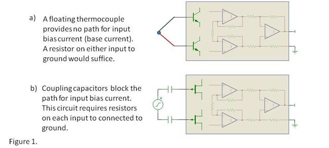
Even a FET input IAs with extremely low input bias current (e.g. INA116) requires a bias current path. While the AC-coupled circuit as shown in figure 1b might appear to function properly when first powered on, the input capacitors will slowly charge from tiny input bias current and the output would appear unstable or drift away from its starting value. A resistor to ground on each input would properly bias this circuit and with the very low input bias current of a FET input, 10MΩ resistors would work well.
Note that many circuits will not require special precautions. If the differential input voltage source can supply the input bias current and it is referenced to ground through a conduction path, no special precautions are required. See figure 2.
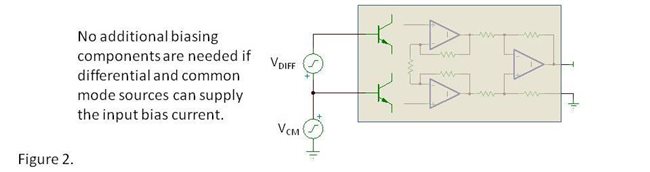
Figure 3 shows three examples of how you might properly bias the inputs of an IA. The resistor values shown might vary according to the specifics of the application and the IA selected.

There are many possible variations in how to provide this current path. Only three general cases are shown. With a little creativity you will find a way that suits your application. If you need advice our Precision Amplifiers forum is the place to go for assistance.
Again, I think the name, instrumentation amplifier, may account for the frequency of this oversight. By the way, it is possible to make the same mistake on the input of an op amp. I don’t think that needs explanation, does it?
Thanks for reading,
Bruce

